Redstone Computers
Since the addition of redstone ore to Minecraft in the Alpha v1.0.1 patch, people have been experimenting with different circuitry implementations to help bring their creations to life. In the beginning, these implementations were usually no more complex than simply wiring up levers to the iron doors that were introduced to players in the same patch. But not long thereafter, more complex creations which centered around logic gates and boolean logic started to appear.
From there, of course, it was only a stones throw to the ALU, read-only and random-access memory, and the other miscellaneous components that make up the modern-day central processing unit. All of which can be largely implemented in Minecraft albeit in an extremely unperformant and unwieldly manner.
The elements of computing systems
Minecraft redstone computers can be assembled almost completely using only a few in-game block types. Redstone dust can be placed on other blocks forming continuous lines which are condusive to redstone power. It’s best to think of redstone dust as the wires or traces found on a printed circuit board and redstone power as the electric current flowing through them. The redstone torch is a block that acts as a source of infinite redstone power which is then carried by the dust. Finally, the redstone repeater is a block necessary to repeat the signal of redstone power further than the inherent 15-block distance (from a source such as a torch or another repeater) limitation.
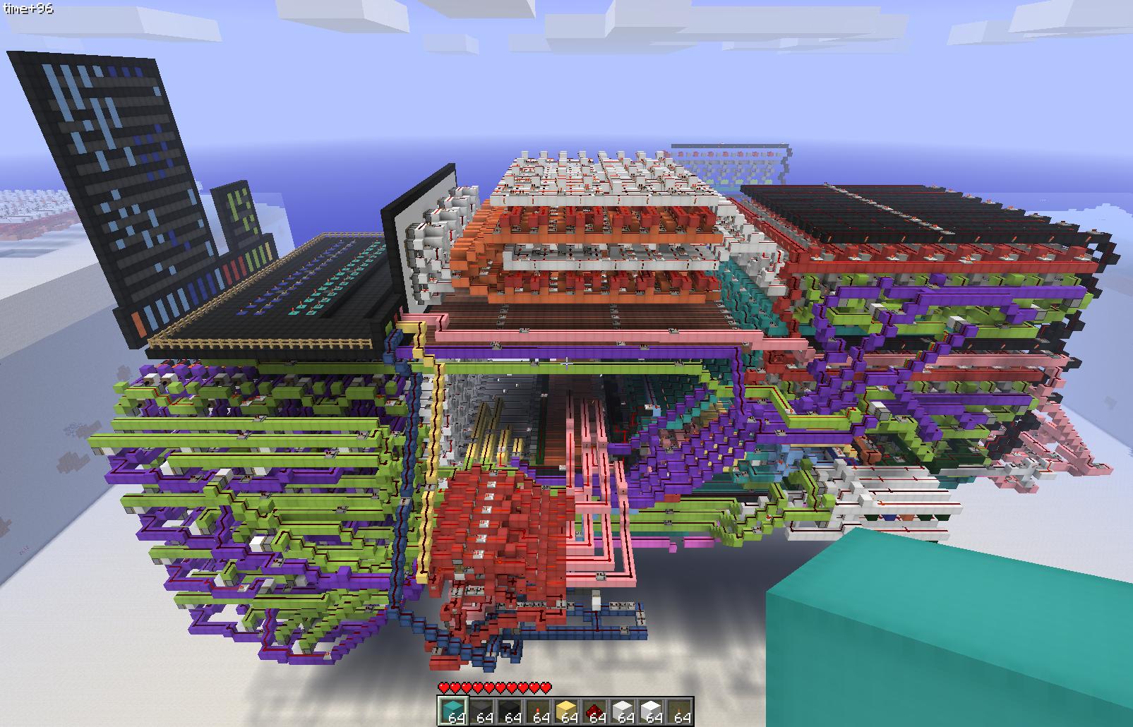
A 16-bit redstone computer. Credit: ohmganesha - minecraftforum.net
The real world elements of a modern CPU include a larger set of primitives and foundations that need to be understood before one could hope to assemble anything even remotely useful. Perhaps most foundational of all is boolean logic and the base-2 numeral system.
Numeral systems
Note: I’ve gone back and forth on the easiest way to explain numeral systems and the terminology tends to get muddled and confused pretty easily so I’m going to go with an explaination that is perhaps not the most correct use of terms but that I think will make sense to most readers.
At the core of most computers is a numeral system called binary – less commonly known as base-2. Binary is a system that allows us to represent any arbitrary number (integer) using only 0 or 1. It is because there are only two different characters to choose from when representing a number that we call this base-2 (I realize the nuance in this statement and highly recommend readers refer to the Wikipedia article on the radix for a more complete picture). If we had been able to utilize 5 different characters, we would say that our numeral system was base-5.
The number system that most people are familiar with is the base-10 system which allows us to represent any arbitrary number using the characters 0 through 9 (ten total to choose from). Another name for base-10 is decimal which we will be using most frequently herein. Another important facet to a numeral system is the positioning of digits. For example, in decimal, the number 13 is represented by using two characters: 1 and 3. However, while the character 3 in this particular case does in fact represent the number 3, the same cannot be said for the character 1 which instead represents the number 10. The reason we know that it represents 10 is because of its position. Had it been one position to the left, it would have represented 100.
The same concept is applied in base-2, though the values represented are not ^10 but instead ^2. Let’s look again at the number 13. To represent this number in binary, we would use 1101. Why? Well because we can only use characters 0 and 1 to represent a number but also because of the positional values of these characters. In binary, the right most position has a value of 1 while the second right-most value is 2. Each position to the left is a doubled (^2) value of the previous positions value. So the third right-most value is 4 and the fourth right-most is 8.
In computing, we see a handful of varying numeral systems being used. The CPU works with base-2 numbers, programmers tend to use systems like base-16 (hexadecimal) and base-64 (this is actually an encoding rather than a strict numeral system but the ideas are similar between the two), while end-users tend to work with the easy-to-use base-10 (decimal). We will be working with all of the aforementioned systems at one point or another in this document so you’ll have opportunity to familiarize yourself more with each of them.
The observant reader may be asking: why were computers designed to work with binary instead of something more space-efficient or easier for humans to reason about like decimal? That’s a fantastic question and the answer is multi-faceted. The short and skinny is that a handful of logistics issues arose in the early days of mechanical computers where gears were used to represent numbers. Over time and as those gears were used more and more, their teeth would start to grind down and cause what we call slipping which meant that the wheel would slip past the point where it was supposed to stop. This imprecision meant that sometimes when a gear was supposed stop on the value 8, for example, it would instead slip to the value 9. This wasn’t a huge issue but it did factor into the eventual adoption of more simple solutions.
Binary systems were less prone to manufacturing problems and wear and tear of the pieces. But also, as the world of electronic circuits began to take shape, the binary numeral system was a natural fit for some of the logical electronic pieces being implemented. Without going into too much detail here, just know that it was much easier to build a piece of hardware that supported the on and off states than it was to build something that could represent three or more states. This boolean logic really lent itself to the binary numeral system. For a really insightful and more in-depth answer to this question, refer to this excellent Computerphile video with Professor David Brailsford of the University of Nottingham.
In binary, we refer to each digit as a bit. 4 bits together are called a nibble and 8 bits together are called a byte. This is an important thing to note as most data is measured in bytes – the kilobyte, for example, following the metric prefix standard, denotes 10^3 bytes or 1,000 bytes while the megabyte denotes 10^6 bytes (1,000,000).
When working with low-level instructions and data, binary quickly becomes a chore. To help mitigate the need of writing 1s and 0s everywhere, it can be very useful to convert binary to the hexadecimal (base-16) system. This greatly reduces the amount of characters needed to represent the same data. I’ll be relying on it hereafter quite a bit so make sure that you are comfortable with it if you wish to be able to follow along closely.
While there are many tricks to performing the binary<->hexadecimal conversion, I believe the easiest way for most people to perform it mentally, is to start by converting a binary string to decimal and then converting from decimal to hex. Let’s use the binary string 11010110 in our example. In hexadecimal, we can represent a full byte (8 bits) with only two characters, each of which representing exactly half of the bits (a 4 bit nibble). To convert to hex, we split the byte into nibbles and determine our decimal values for each. Again, in base-2 systems, the right most digit is position 0 and represents the value 1. We work left from there with each position p having a value of 2^p. Starting with the right nibble, this gives us the following table:
| 8 | 4 | 2 | 1 |
|---|---|---|---|
| 0 | 1 | 1 | 0 |
Using 0 + 4 + 2 + 0 we determine our value in decimal to be 6. In hexadecimal, the numbers 0-9 are available to use as well as the letters A-F with A being equal to 10, B being equal to 11 and so on. Because our decimal value is 6, we dont need to use a letter and can simply represent our decimal 6 with our hexidecimal 6. On to the second nibble:
| 8 | 4 | 2 | 1 |
|---|---|---|---|
| 1 | 1 | 0 | 1 |
This gives us 8 + 4 + 0 + 1 which equals 13. Hexidecimal uses D to represent 13 so we are left with D6 as our hexidecimal representation of 11010110. When written, we can prefix D6 with 0x (this is a zero) to denote a hexidecimal value (0xD6). Pretty straight forward, right?
Logic gates and boolean functions
Logic gates are the primitive building blocks behind the electronic circuits that perform computation by implementing a boolean function (some logical operation over binary inputs). While the computation that can be performed by a single gate is extremely simple in nature by itself, one can combine any number of these basic gates together to form more complex solutions that are capable of more sophisticated computation. Logic gates, at the hardware level, are implemented using a special electronic component called the transistor. The very earliest transistors were called thermionic triodes which relied on very fragile vacuum tubes. It wasn’t until William Shockley at Bell Laboratories first created the point-contact transistor using semiconductors that we were able to start packing thousands of transistors into a single easy-to-work-with integrated circuit (sometimes called an IC or chip). The first commercially available microprocessor, for example, the Intel 4004, contained a mind-blowing 2,300 transistors in a chip roughly the size of the US quarter. Even more impressive still are todays modern microprocessors which can include upwards of 20,000,000,000 transistors in a form factor no larger than a baseball card.
When you are able to cram more transistors into a circuit, you are then able to assemble more logic gates from them – and the more logic gates you have, the greater your computational output. In Minecraft, we do not need to take things down to the transistor level but we do need to start building at the logic gate level; and unfortunately for us, we aren’t able to do this at a microscopic level like Intel can so we need lots and lots of space for construction of these circuits.
How much space exactly depends on our architectural designs. Because a CPU is simply the composition of many logic gates, it would serve us well to construct gates in as effecient and space-saving a manner as possible. This is particularly important with redstone computers for a few reasons: first, because the larger your computer the more time you spend flying around the map just to work on various things and second, because redstone power signals take time to propagate (the exact speed of transmission is much slower than electricity does and some minecraft blocks like the repeater add an additional delay) so the less area we need that signal to traverse, the better.
Let’s take a look at some of the primitive gates that we can use to construct a redstone CPU.
The NOT gate, also called an inverter, implements a binary function defined as f(a) == 1 - a. In English, this simply means that we output the negated value of our binary input. If the input was true, we output false and if the input was false, we output true.
The AND gate implements a binary function defined as f(a,b) == ab*. In English, if both binary inputs are true, the output is also true.
The OR gate. The binary function implemented by this gate is defined as f(a,b) == a+b-ab*. In English, this means that given two binary inputs, if either is true (**1**), then the output is also true.
The NAND (NOT AND) gate implements the AND gate but instead checks for falsy inputs rather than truthy. If both inputs are false, the output is then true.
Similarly, the NOR (NOT OR) gate implements the OR gate but instead checks for falsy inputs rather than truthy. If either input is false, the output is then true.
Lastly, we have the XOR (exclusive OR) gate which implements a binary function defined as f(a,b) == a+b-2ab. In English, this means that given two binary inputs, if one and only one is true, then the output is also true.
In the end, we have simple electronic conditional switches that can output one of two states (on or off, true or false, 1 or 0) that can be described mathematically using binary algebra. Easy peasy. It’s worth mentioning, too, that the logic implemented through these gates is sometimes referred to as combinational logic because they work with combinations of inputs to produce an output; put another way, you can combine these simple gates together in different ways to produce more complex functions. One thing, however, that these gates cannot do is maintain state. For this, we will need to implement computer memory primitives through sequential logic. More on this, later.
Synchronization and timing
Clocks are the syncronization mechanism found in nearly all CPU implementations. Alternating between high and low states, the clock facilitates coordination betwen all the operations of a circuit. As the clock oscilates between its two states, we are able to act at different points of the cycle (for example, you could perform actions on both the rising and falling events of the cycle; this is known as double data rate or DDR) but for our redstone computer, we will only be acting on the rising edge.
One complete clock cycle per second is referred to as a hertz (Hz) and generally speaking, computers become more useful the more cycles you can fit into that second. However, the faster your clock runs, the more potential for instability you will have. This is because clocks are not perfectly timed and many different factors can cause skew including imperfections in the materials used to construct the circuitry and the temperature of those same parts.
Computer memory
Using the logic gates we just learned about, it is possible to build a more sophsticated composite capable of remembering a single binary state. These 1-bit memory cells come in in a variety of flavors but the two we will primarily deal with as redstone computer engineers will be the D latch and the D flip-flop. A lot of reference material will refer to these two things interchangeably but there are in fact subtle differences; namely that latches are asynchronous allowing outputs to change the moment that inputs do whereas flipflops update on clock cycles. Redstone computers generally use both.
Much in the same way that the combinational logic gates written about above could be combined in different ways to tackle more complex problems, our memory primitives can also be combined to handle the storage of data. For example, while a D flip-flop can be used to remember a single boolean value (state), an array of D flip-flops can be assembled to faciliate the storage of any amount of data.
The brains of the operation
The ALU is the heart of the CPU and its ability to do useful computation. An acronym for Arithmetic Logic Unit, the ALU is responsible for performing all the arithmetic and bitwise operations required of the central processing unit.
Supporting the end-user with interfaces to the hardware
IO (input/output) is the generic term for all our various interfaces to the CPU which help make it useable by any measurement. IO includes things like displays (for computational output) and keyboards (for user provided data and control).
Teaching a computer how to talk
The ISA or Instruction Set Architecture defines the set of primitive commands understood by processor for executing arbitrarily complex instructions. Writing instructions using these commands is much easier than writing them in raw binary (the format the processor itself uses).
Building a redstone computer
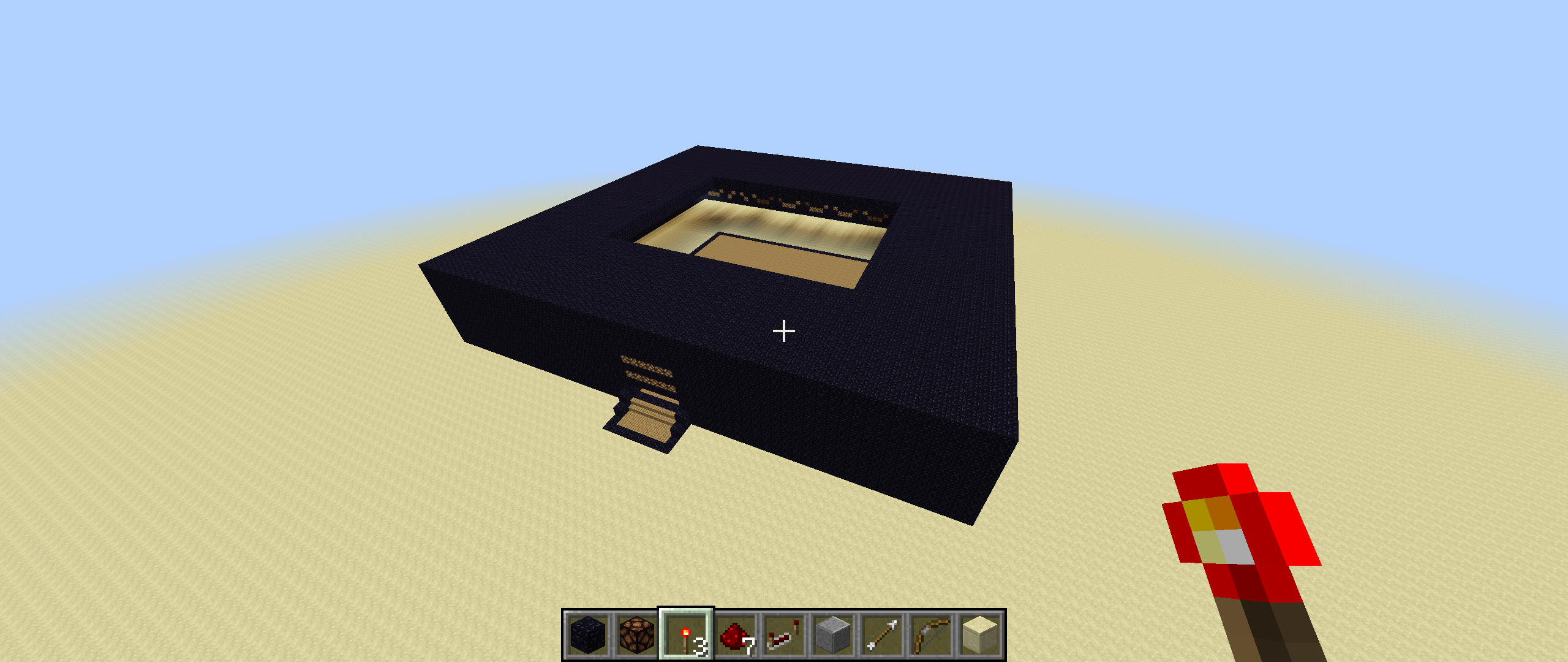
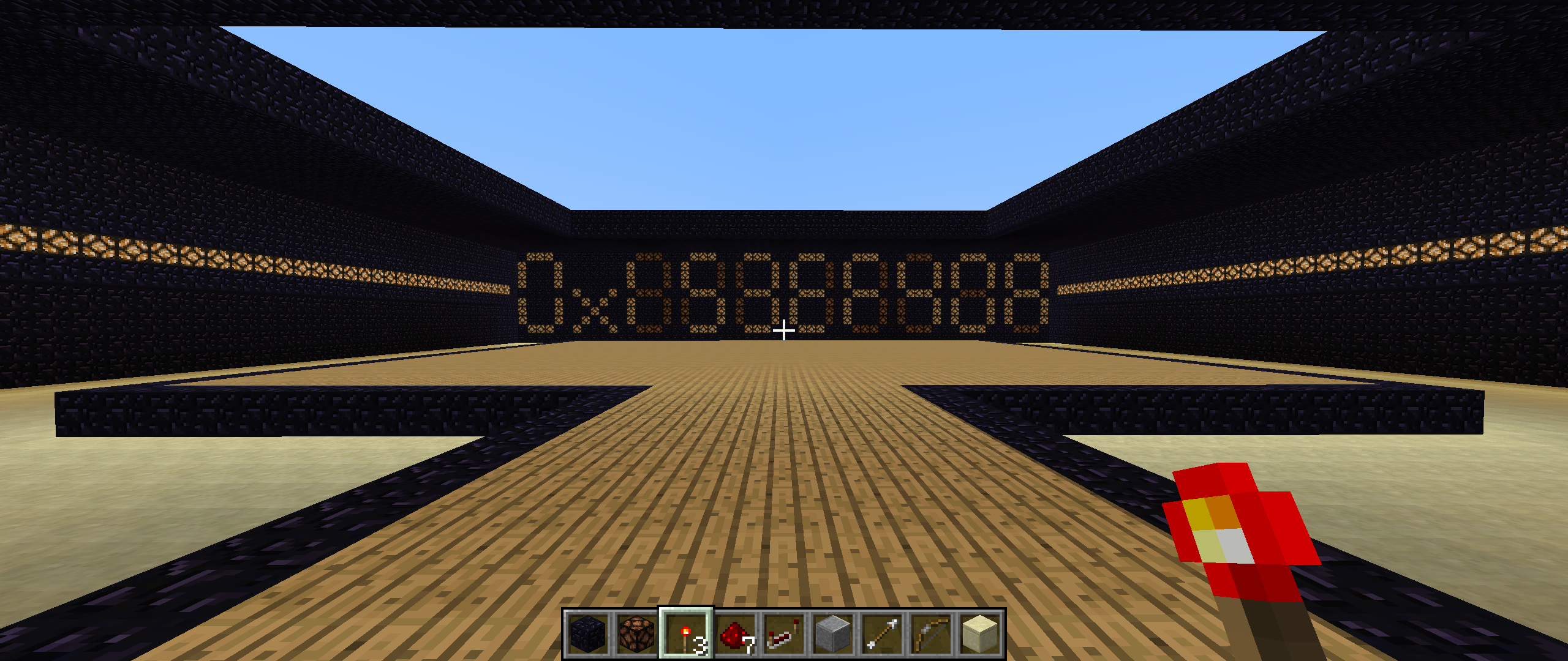
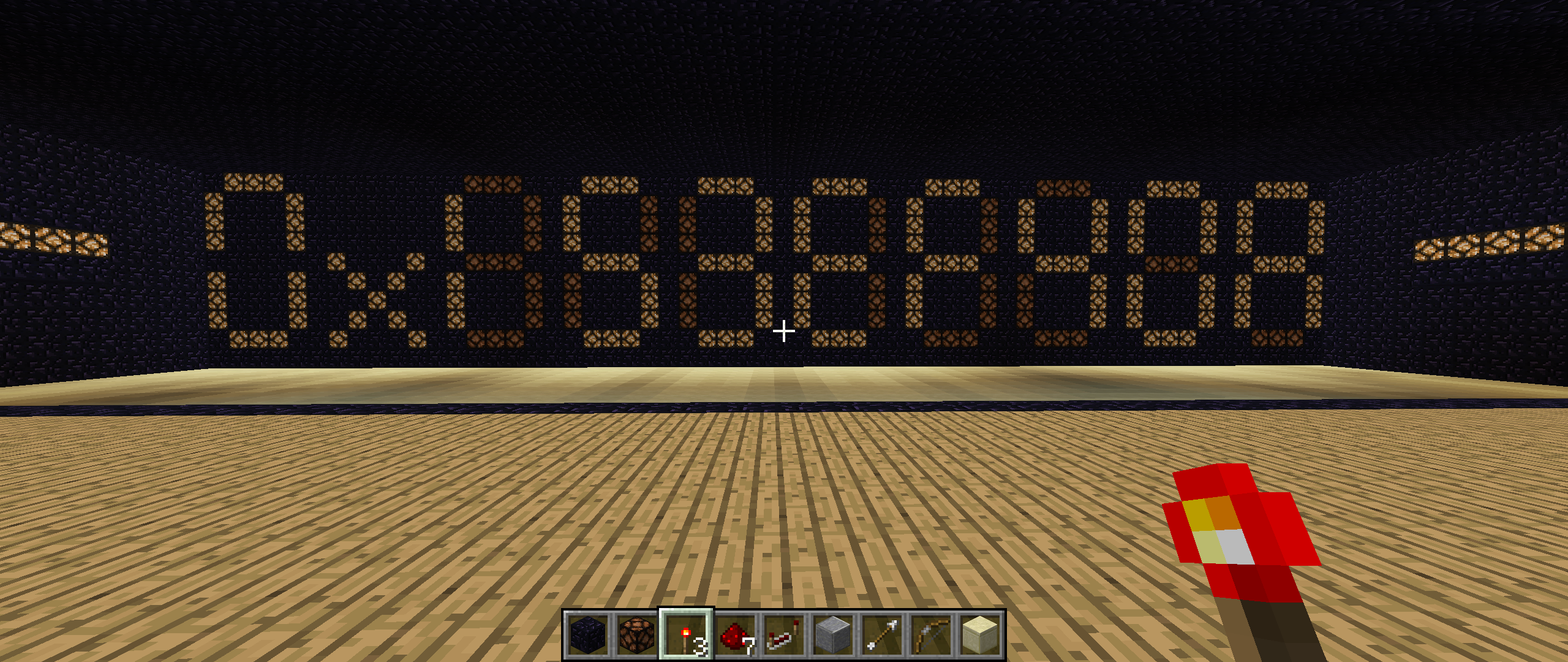
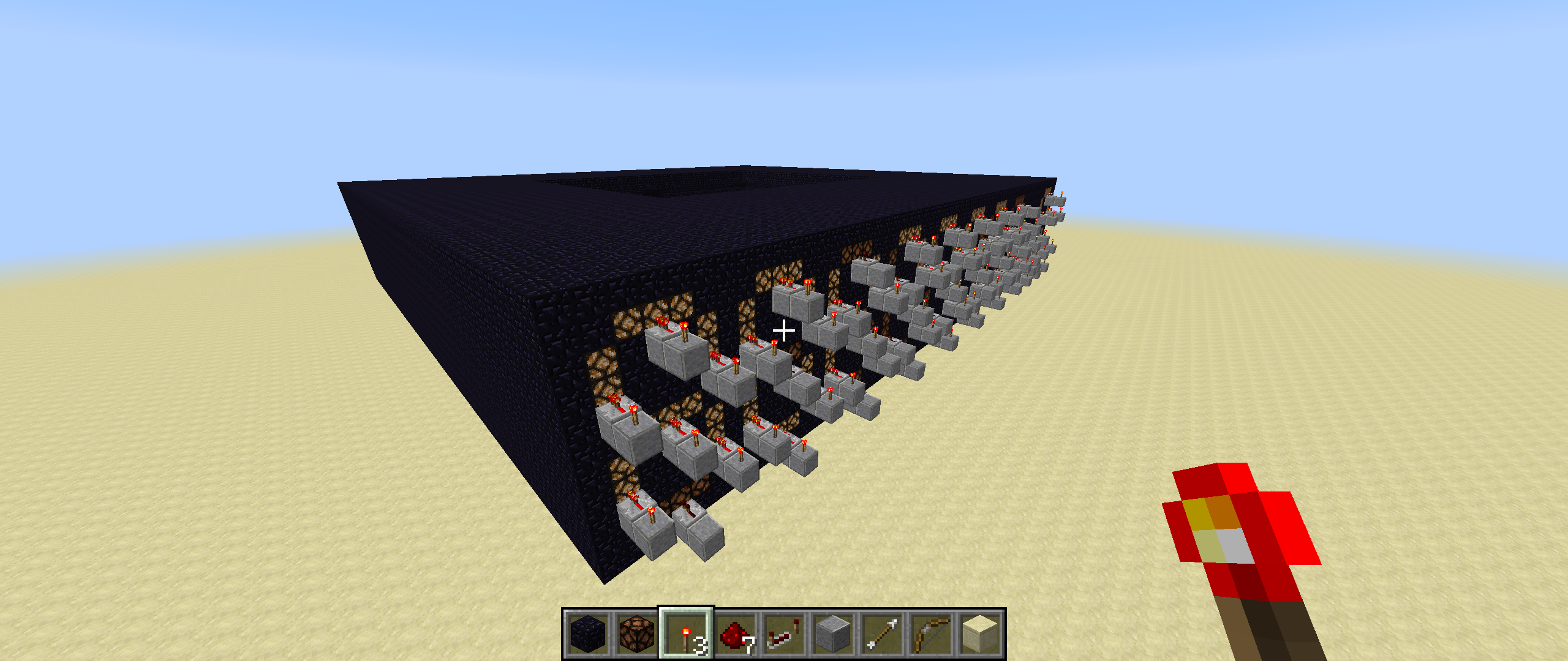
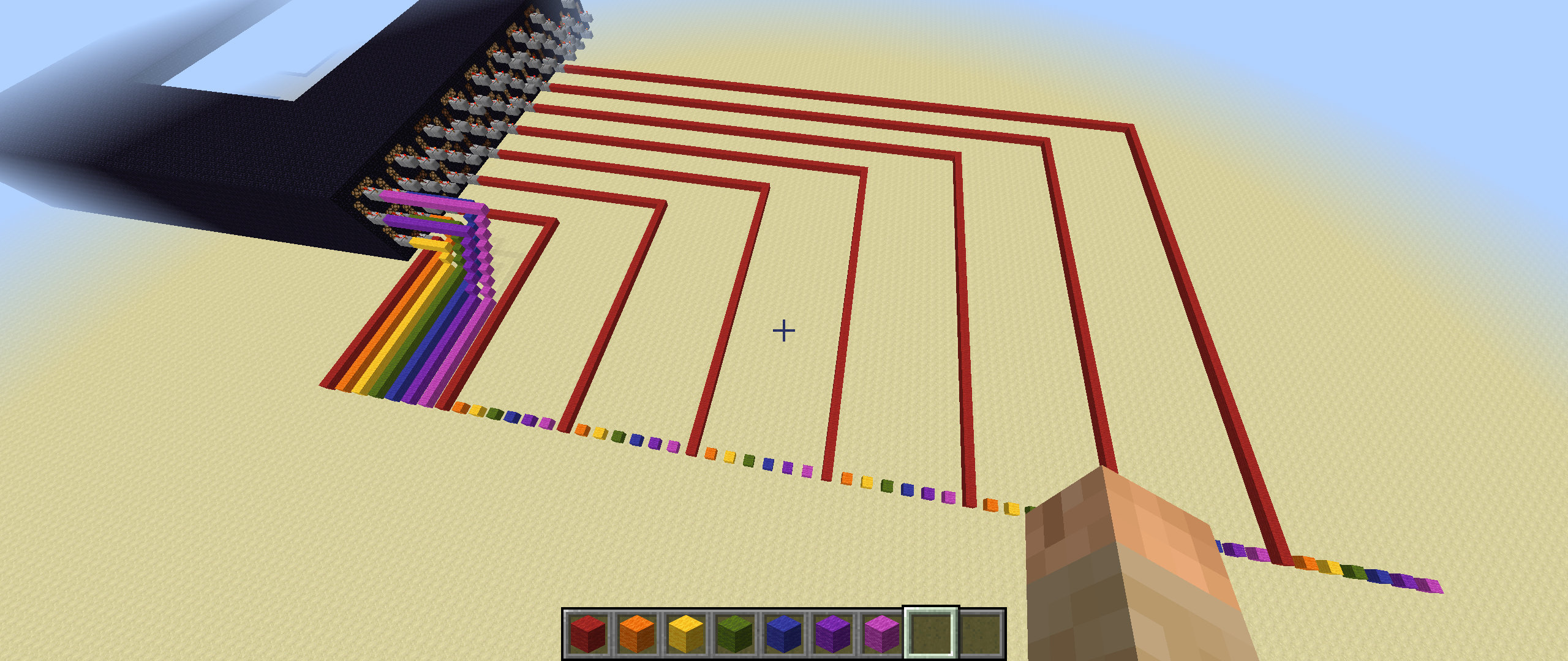
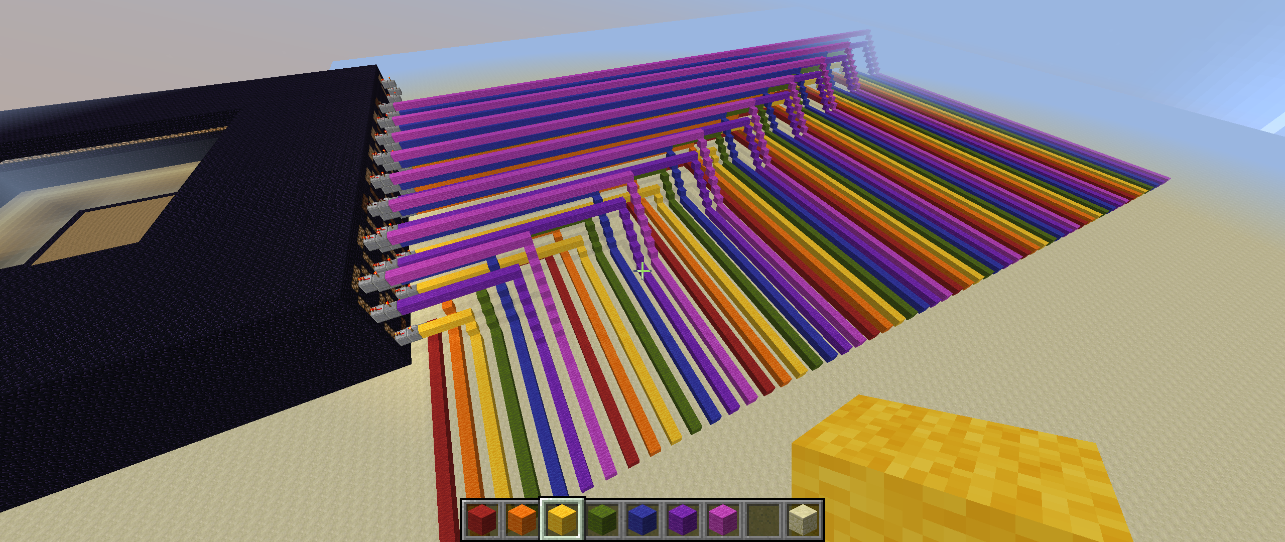
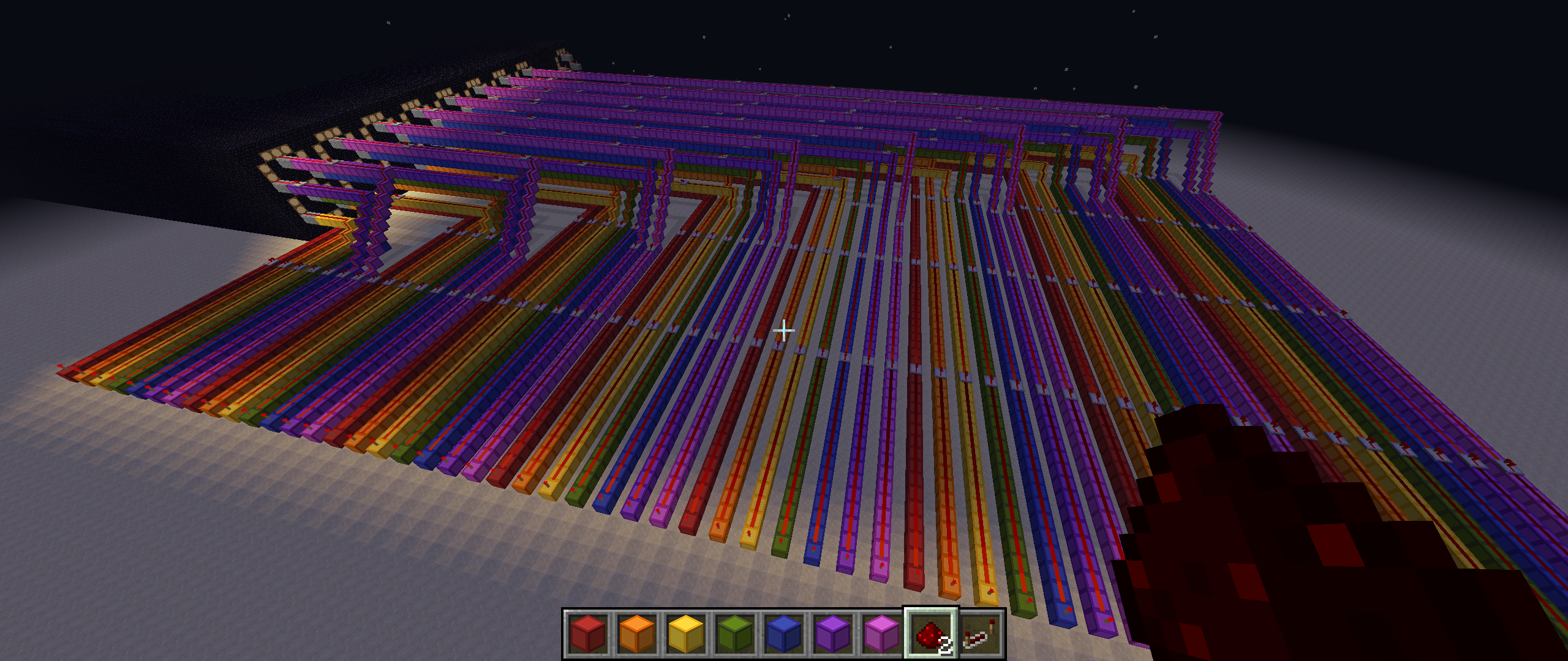
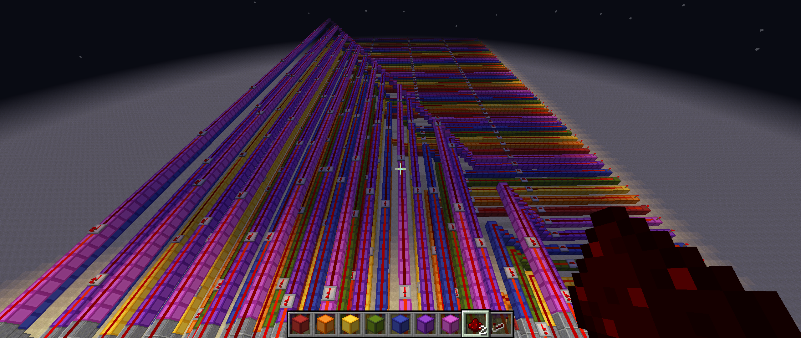
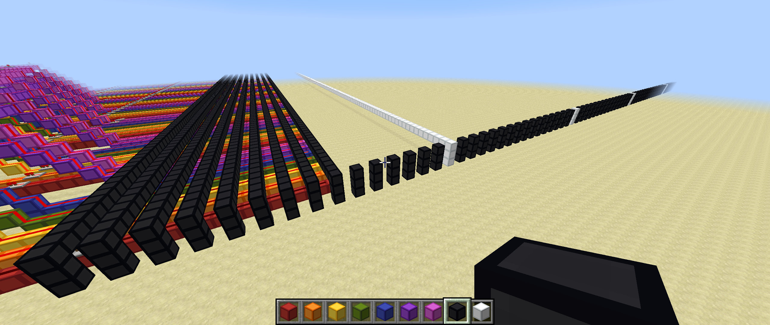
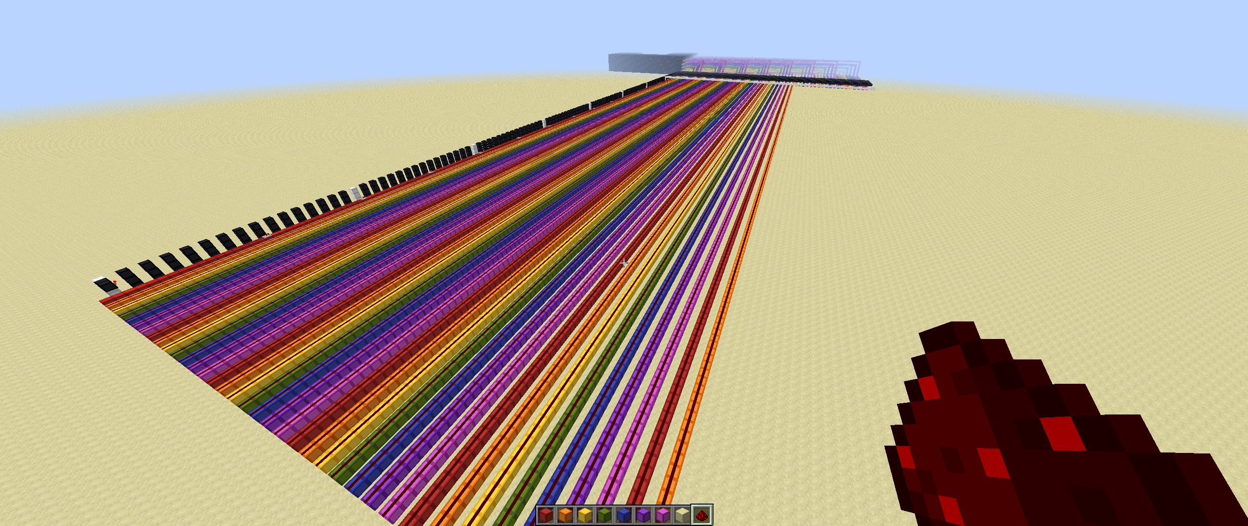
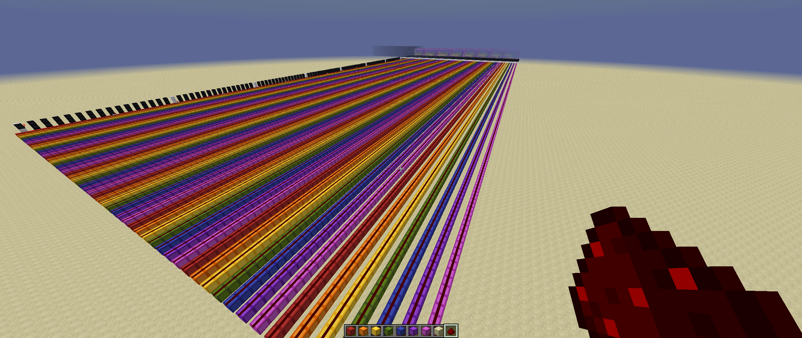
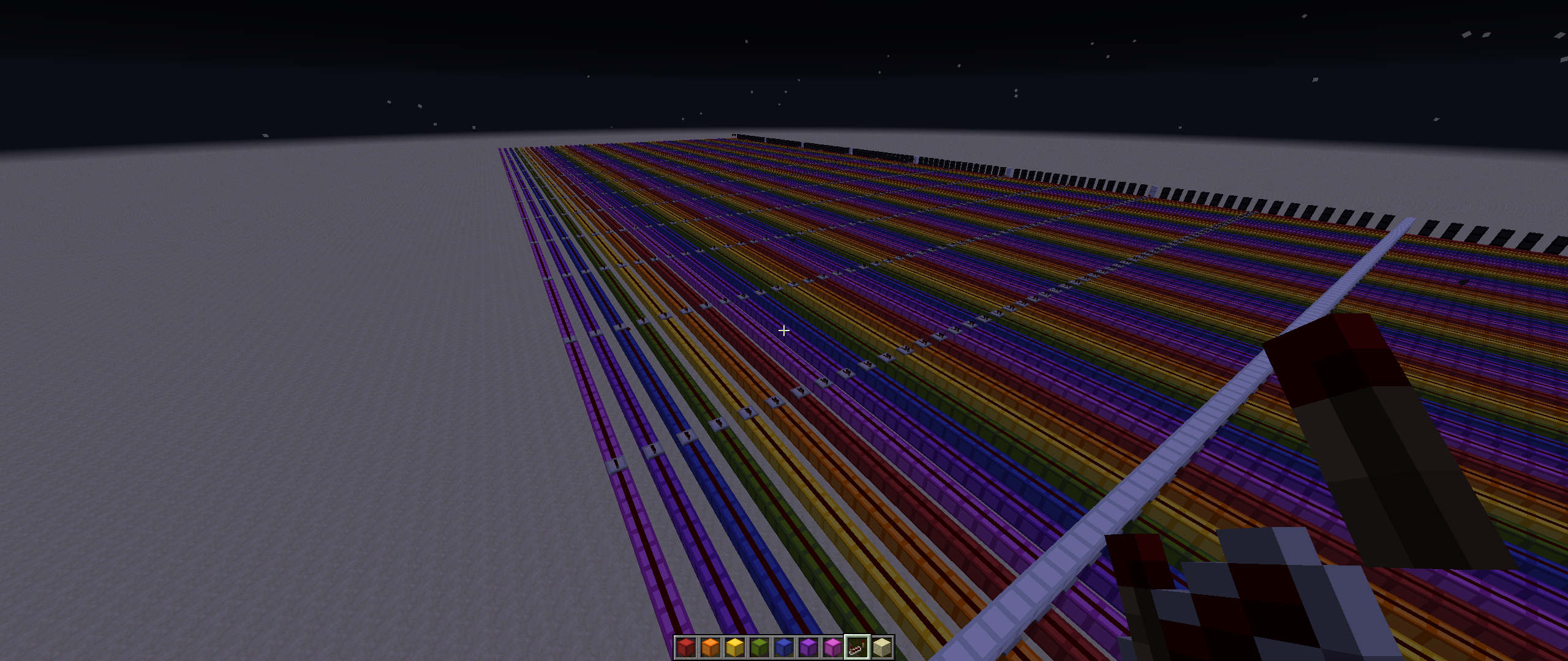
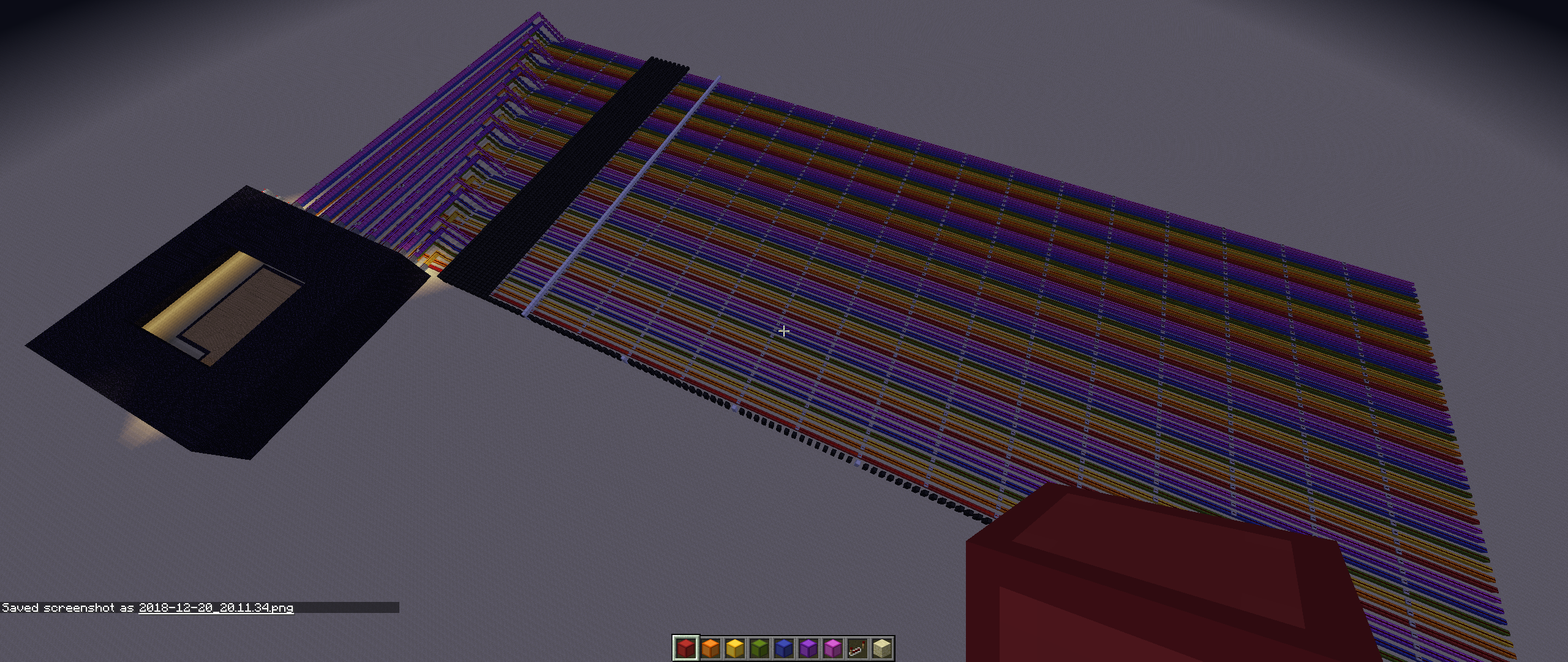
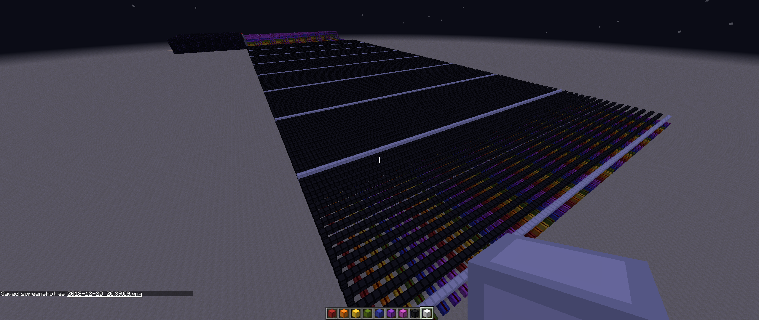
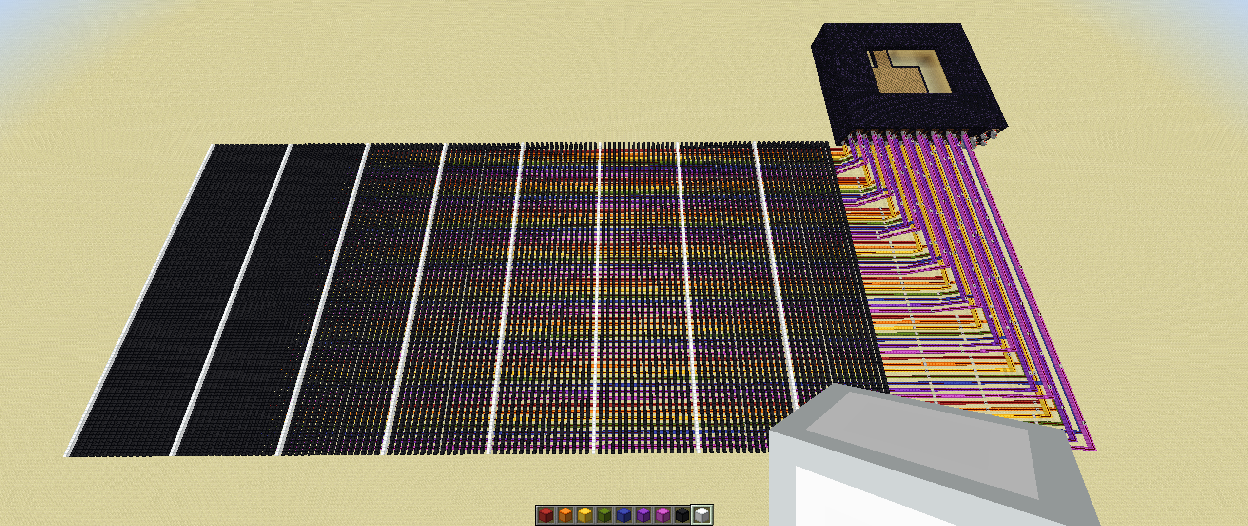
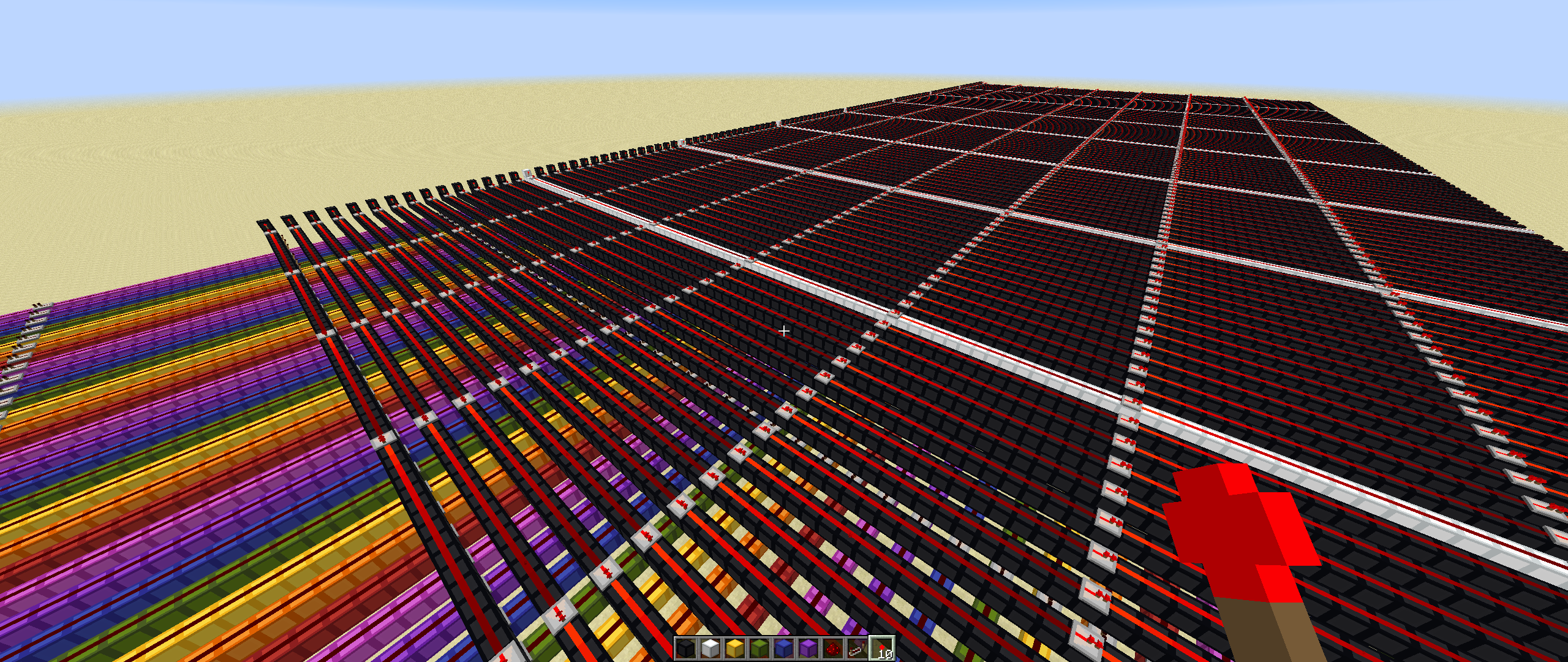
Note: This section will be a work-in-progress for quite some time and will at times look fairly unorganized and/or chaotic. You’ll want to check back regularly for updates. For the time being, I’m just going to dump some screenshots here of various things I’m building and will eventually work them into the build log as I continue making progress.
